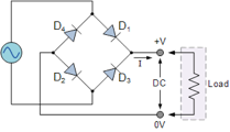
I have always found it is quite hard to show the path of the current in a bridge rectifier to A-level students using diodes alone. The diodes are tiny, for a start, and you end up following the wire with your finger around, but students seem to get lost in the process. I still introduce the rectifier using diodes and one thing I show them is that even using a DC voltmeter doesn’t change the sign. This is convincing for some, but it is still nice to be able to give further proof of what’s going on.
The diagram might also help, because it is easier to follow the path around.
However, I have started building rectifiers with LEDs alongside the diode version and it works a treat. The first thing I show them is the circuit on DC current. Only two of the four LED light up, so I can ask “What would happen, if I reverse the polarity?” They now seem to get it and they often answer correctly that the other two LED will light up. I change the polarity several times to simulate the two half-waves, as in the images below.
Then, I get the spinning wheel we use to observe ripples in the ripple tank (the one with gaps, I can’t remember the name) and put the LED rectifier on AC. The result can be seen in the video below.


